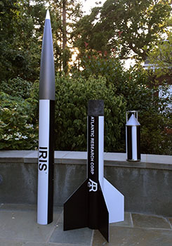
Iris
After the first flight of the Aerobee and while waiting for XPRS and the second flight, I took another look through Rockets of the World for more inspiration. The Iris caught my eye (p. 137 in the third edition) and had a booster similar to the Aerobee, but without fins.
I'd been meaning to try one of the Wildman Rocketry kits, but none of them really did it for me. This was the opportunity to take advantage of their custom services and "make my own kit" so I ordered a standard 5" nose cone plus four sections of airframe cut to length and the aft section custom slotted (plus two couplers).
The Pictures
The rocket was painted the weekend just before Aeronaut and the decals applied on Monday July 27, 2015. It's always a rush to be ready for the launch.
 |
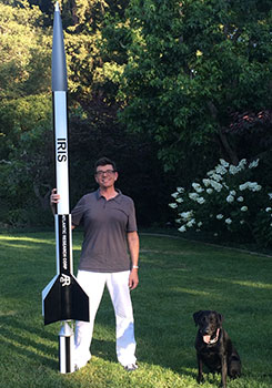 |
I didn't do a perfect job with the painting, but it's "good from far." As it turned out, I couldn't attend the launch anyway, but "nothing would get done without deadlines."
The Design
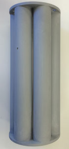
Since this rocket is predominantly a single airframe diameter, the first choice was the sustainer tubing size. 6" was tempting, since that would be close to 50% scale, but I wanted a more manageable size, so I chose 5" tubing (5.15" O.D.), which meant a 43% scale and a 10' overall length.
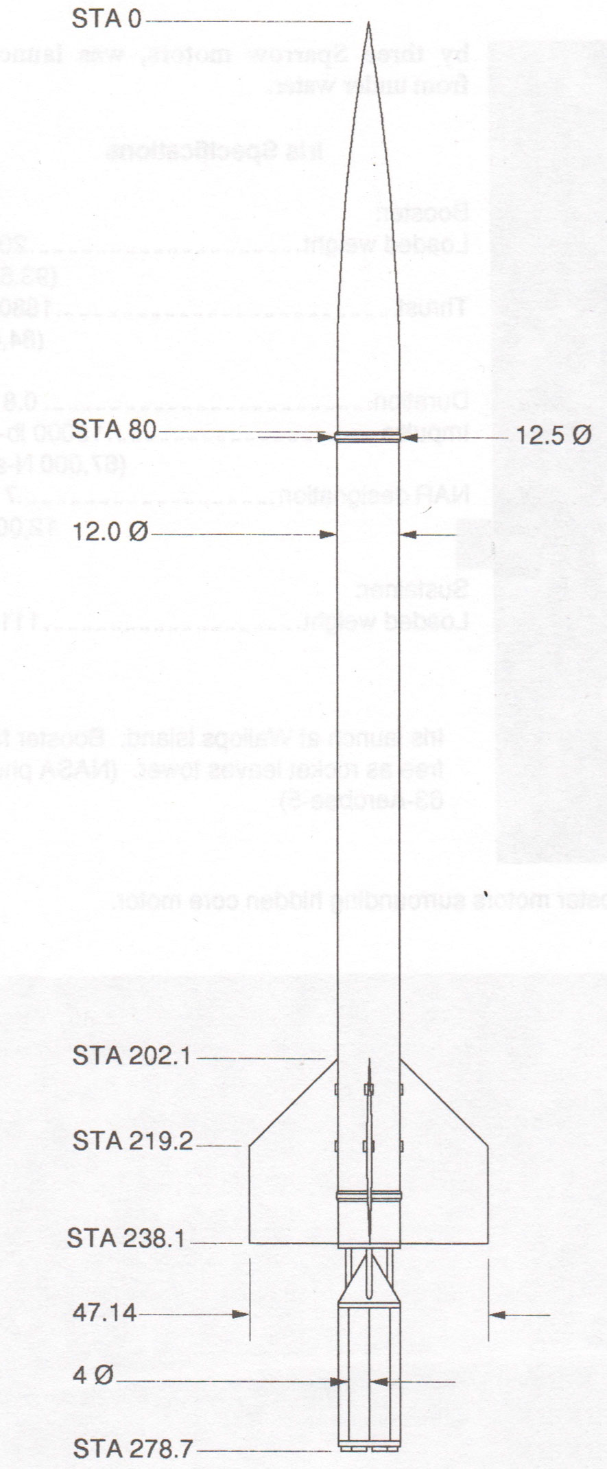
The sustainer was a straight forward backwards-ejection dual deployment rocket, so no surprises there. The booster would be a cluster of six 38mm motors (the seventh was left out to make room for the recovery system). See the overall drawing for a summary.
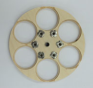
Booster
I started with the booster while waiting for the parts to arrive from Wildman. The booster is also more interesting because of the 6-motor cluster.
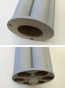
There is a lot of stuff to pack into a relatively small space, not least of which is the six 38mm MMTs. The center was left open for electronics and the effective length of the motor tubes is shorter than their external length to provide space for a parachute.
 |
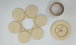 |
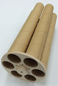
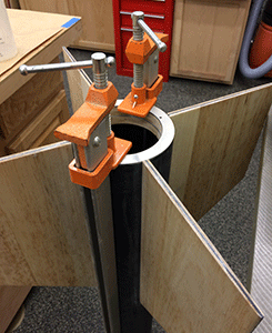
Above you can see the plywood bulkheads for the aft end (left) and center (right). These have grooves cut into them to keep the tubes arranged properly. The "center" plate marks the transition from usable MMTs to the top section which has a 3" coupler to contain the recovery system.
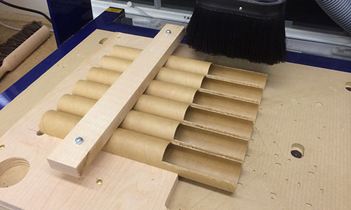
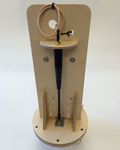
I wanted the tubes to have exactly the same cutout, so I ran the cutting operation on all of them at once (and in parallel). I'm still finding new uses for the ShopBot!
 |
 |
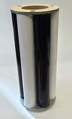
Here is the booster tubes with the bottom and center plates assembled dry to test the fit. Once everything fit properly, the main body could be bonded together from the inside and outside.
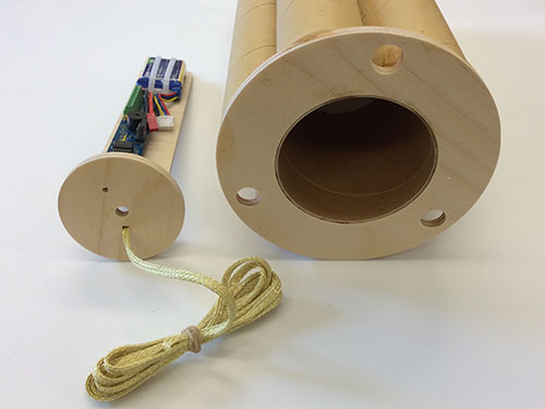
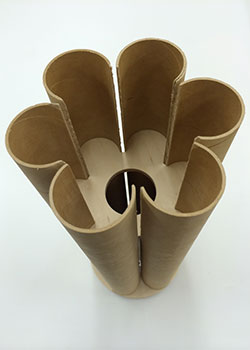
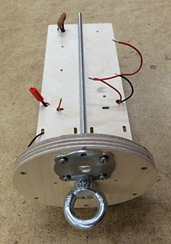
Finally the inner tube that formed the parachute compartment and the forward ring were installed. Above you can see the forward end of the completed booster and the electronics bay that slides into it (using the long-and-thin G-Wiz LCX).
 |
 |
This booster was the most complex painting job on this rocket. Not only were there three colors, but the masking was intricate. Unlike the sustainer I decided to paint it with rattle cans, mostly because I ran out of time before Aeronaut.
 |
I decided to try out the two-part rattle can clear coat, and it worked very nicely as you can see.
Interstage
Like the Standard Aerobee, the interstage is the focal point of this rocket. However the Iris interstage has a solid top ring which I decided to mill out of a piece of ¼" aluminum plate.
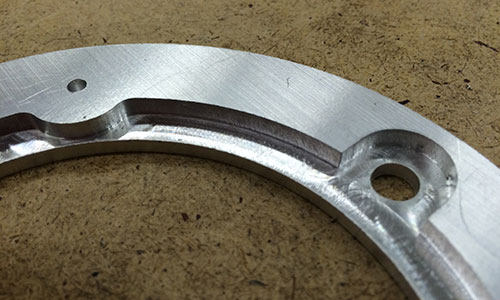
Above is the ring freshly milled from the 6061 sheet. Below the PEM nuts have been installed and the edge sanded.
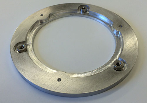
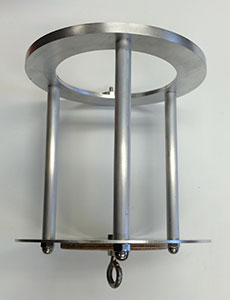
The complete interstage is made up of the top, three aluminum tube struts, and a bottom plate of 1/16" aluminum.
 |
 |
Above are two views of the complete interstage; on the left is a side view showing the struts on the right is a top view showing the sustainer alignment pins.
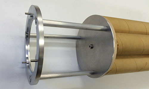
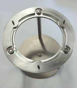
And finally above we have the interstage mounted as the cap of the booster.
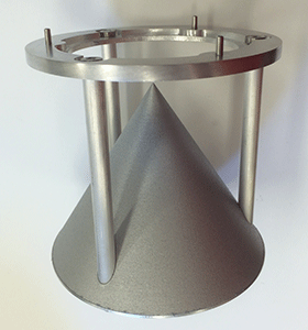
Aside from the structure of aluminum, I added a 3D printed cone to complete the appearance of the interstage. This cone probably won't survive sustainer motor ignition, but it will look good before that. Above you can see the complete interstage, with the cone painted an "aluminum" color.
Sustainer
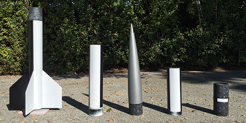
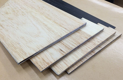
The parts arrived from Wildman exactly as ordered and precisely cut. They are black fiberglass, not carbon fiber, which I guess is a Wildman signature.
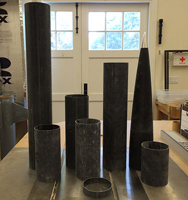
The parts are shown above; from left to right:
- Aft airframe with four fin slots and backwards ejection coupler,
- Drogue airframe, electronics bay coupler and switch band,
- Main (forward) airframe, and
- Nose cone with separate shoulder/coupler.
See the overall drawing for how these pieces fit together.
Other than the fins, which I wanted to make with a profile, the rocket is a standard dual-deployment HPR arrangement.
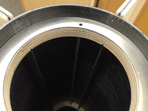
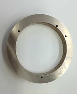
I built this rocket without a motor-mount tube, just using centering rings directly. As you can see in the aft-end photo above, the fin cores slot through the tube to allow internal fillets and the motor seats against an aluminum ring.
 |
 |
Above you can see the final aft-end ring (large enough to fit around the 98mm aft closure) and how it caps off the aft end of the sustainer. The three holes are for the pins on the interstage. The slot is for the igniter wire from an electronics bay forward of the motor.
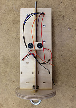
The main electronics bay is in mid-position with drogue aft and main forward (traditial arrangement). This rocket is flying older G-Wiz electronics, an HCX and an LCX. Below you can see the front and back of the plate wired and ready for the units to be installed.
 |
 |
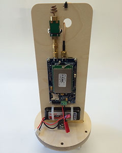
The nose cone is dedicated to a GPS tracker, in this case the Real Flight Systems GPS-1.
 |  |
After painting my last few rockets with rattle cans for similicity, I decided to go back to automotive paints for the sustainer. They turned out OK; I give myself a 'B' mostly because the clear coat didn't go on smoothly.
Above you can see the five parts of the sustainer curing outdoors after the clear coat.
Fins
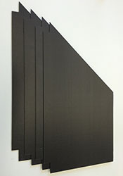
The fins were the only complex part of the sustainer; otherwise, it's a very standard design. I wanted the fins to have a profile, so they are made with a core of carbon fiber plate with balsa half-profiles laminated to each side. (This is much the same as the Aerobee fins except I used balsa for the profiles instead of foam.)
 |
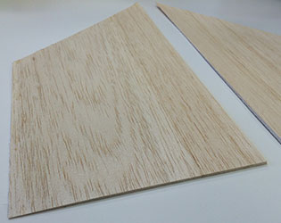 |
Then I bonded the profiles to each side of the cores using laminating epoxy and put them into a vacuum bag for even consistent pressure. Finally, I laminated a layer of 4oz fiberglass cloth to the outsides to create a hard skin over the balsa and back they went into the vacuum bag.
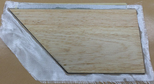
In the picture above, you can see one fin with profiles and fiberglass lamination just out of the vacuum bag and ready to have the excess fiberglass trimmed.
And finally all four fins completed and ready to install. I really like the profiled fins; not only is it more prototypical, but it just looks cool.
Historical Info
Text from Rockets of the World. (The Iris article starts on page 137 of the third edition.) I have also scanned in Peter Alway's drawing for reference.
Originally an NRL project to loft 100 pounds (45 kg) to an altitude of 200 miles (320 km), the Atlantic Research Corporation's Iris was transferred to NASA along with the rest of the NRL sounding rocket program. It was first flown July 22, 1960.
The Iris was designed to give researchers the gentle acceleration of the Aerobee sounding rockets combined with the simplicity of solid fuels. Like the Aerobees, the Iris required a boost for unguided, fin-stabilized flight. Unlike the Aerobee booster, the Iris booster, consisting of seven clustered motors, burned out and separated from the sustainer before leaving the tower, so booster fins were not required for stability.
NASA flew the Iris four times in 1960-1962. The last carried scientific instruments to study atmospheric structure. Of the four flights, only the first two were fully successful.
A joint Navy-Lawrence Livermore National Laboratory project, called Hydra Iris, continued into the late 1960s with at least 6 more flights. The Hydra Iris, booster by three Sparrow motors, was launched from under water.